1. Converter Station Case Introduction
1.1 Changji Converter Station
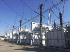
Changji - Guquan ±1100 kv HVDC transmission line starts from Zhundong (Changji) converter station in Xinjiang and ends at Xuancheng (Guquan) converter station in Anhui, passing through six provinces of Xinjiang, Gansu, Ningxia, Shaanxi, Henan and Anhui. The total length of the line route is about 3,304.7 km. The transmission capacity is 12 million kw, and the voltage is ±1100 kV. Changji converter station, as the converter generation end of the transmission project, is also the main body of the thermal camera detection.
Changji Converter Station
1.2 Thermal Camera Hardware Installation
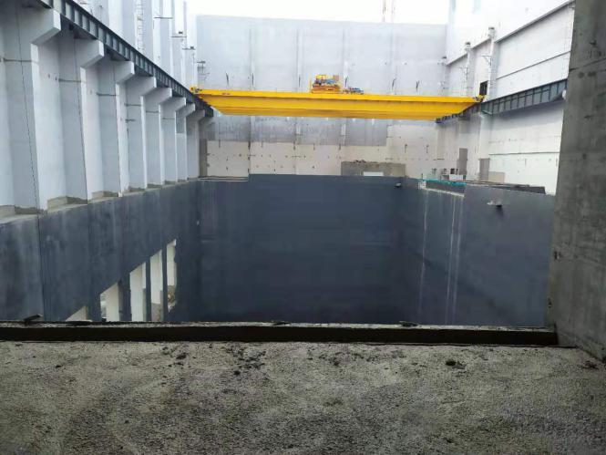
In this project, the installation method of the thermal camera carried by the track robot was adopted. The main equipment of the converter station was monitored by the movement of the robot on the fixed track combined with the rotation of the head. This method not only comprehensively monitored the equipment, but also reduced the installation quantity of the thermal camera and saved the engineering cost.
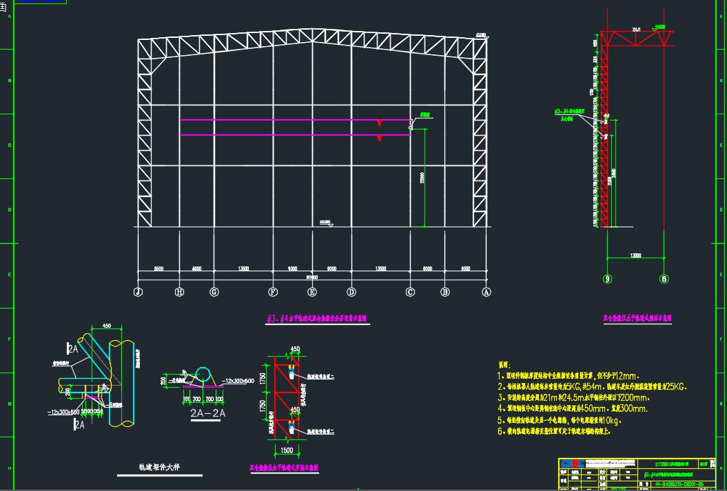
Project Track Installation Construction Drawing
1.3 Networking And Software Functions
The thermal image of the front end is directly displayed on the large screen of the main control room through the transmission network. Meanwhile, the warning message is also connected to the main control room, and the staff can grasp the operation of the equipment in the main control room.
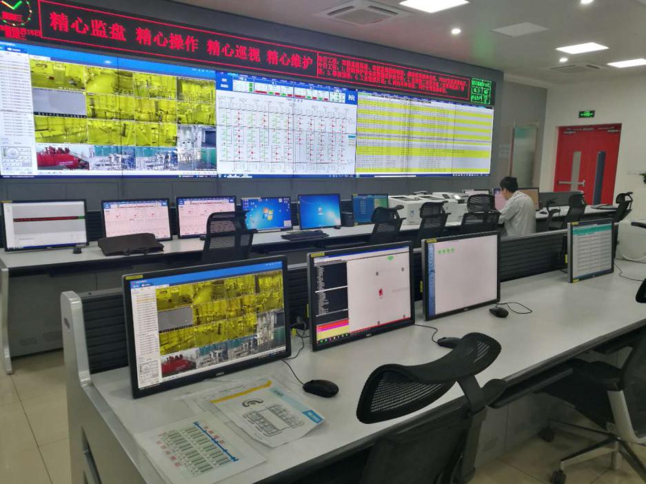
Changji Converter Station main control room
Software Functions
Ø Online Preview
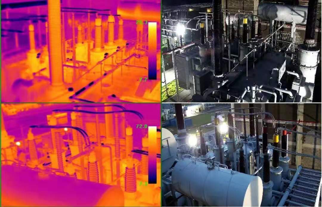
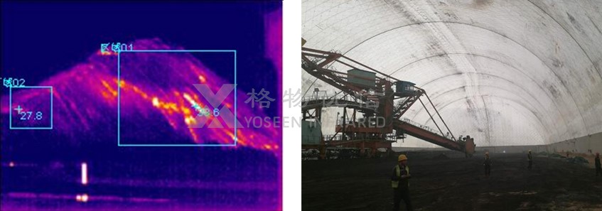
Online real-time preview of the front screen, infrared light and visible light dual spectrum monitoring mode, not only can see the temperature field of the equipment, but also can clearly locate the temperature anomaly area.
Double Light Live Preview Screen
Ø Temperature Measuring Object
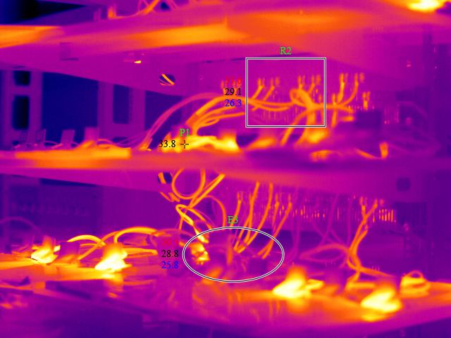
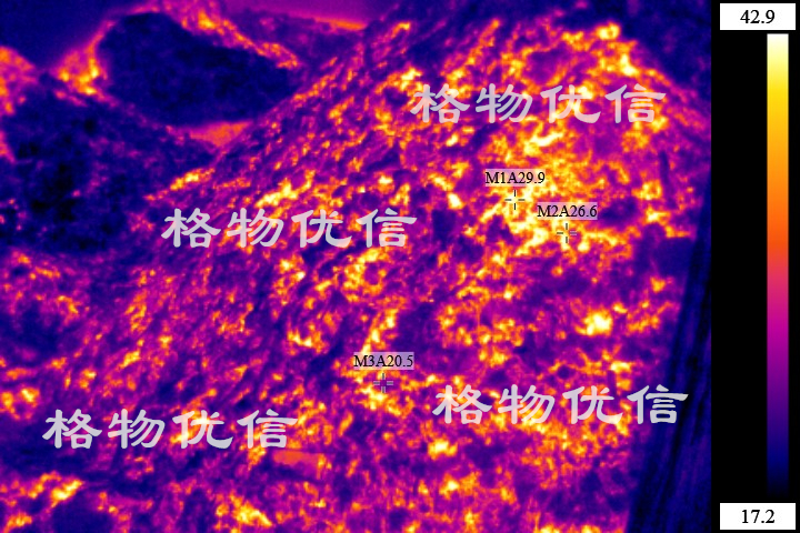
The addition of arbitrary polygon temperature measuring object; For temperature-measuring targets of different shapes, arbitrary polygons can be added to select them to measure their characteristic temperatures in real time: the highest temperature, the lowest temperature, the average temperature, etc., to monitor the targets.
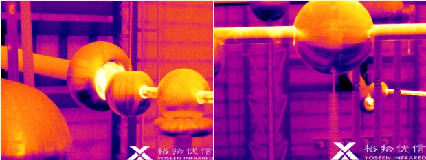
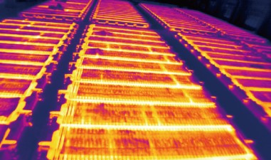
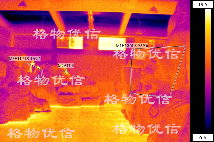
Thermal images of main equipment of converter station
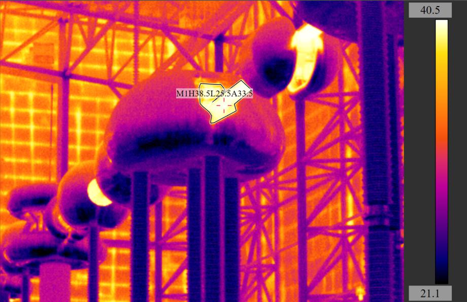
Arbitrary Polygon Temperature Measuring Object
Ø high temperature alarm
Electrical equipment in the aging, before the occurrence of accidents are accompanied by temperature changes. After the temperature field of the equipment under test is detected by the infrared thermal camera, a high temperature alarm value can be set. When the temperature rises to a certain value, an alarm signal can be given to remind the staff or other equipment to take corresponding processing measures.
High Temperature Alarm Setting Interface
Ø temperature alarm
For the monitoring of some equipment, it is not suitable to determine its working state by setting an absolute temperature value. It needs to determine its working state according to the temperature difference between it and other equipment, such as the junction post of three-phase electricity, etc. It needs to determine whether its working state is balanced and stable according to the temperature difference of three-phase equipment such as A, B and C.
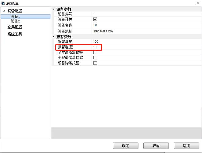
Temperature difference alarm setting interface
1. Converter Station Case Introduction
1.1 Changji Converter Station
Changji - Guquan ±1100 kv HVDC transmission line starts from Zhundong (Changji) converter station in Xinjiang and ends at Xuancheng (Guquan) converter station in Anhui, passing through six provinces of Xinjiang, Gansu, Ningxia, Shaanxi, Henan and Anhui. The total length of the line route is about 3,304.7 km. The transmission capacity is 12 million kw, and the voltage is ±1100 kV. Changji converter station, as the converter generation end of the transmission project, is also the main body of the thermal camera detection.
Changji Converter Station
1.2 Thermal Camera Hardware Installation
In this project, the installation method of the thermal camera carried by the track robot was adopted. The main equipment of the converter station was monitored by the movement of the robot on the fixed track combined with the rotation of the head. This method not only comprehensively monitored the equipment, but also reduced the installation quantity of the thermal camera and saved the engineering cost.
Project Track Installation Construction Drawing
1.3 Networking And Software Functions
The thermal image of the front end is directly displayed on the large screen of the main control room through the transmission network. Meanwhile, the warning message is also connected to the main control room, and the staff can grasp the operation of the equipment in the main control room.
Changji Converter Station main control room
Software Functions
Ø Online Preview
Online real-time preview of the front screen, infrared light and visible light dual spectrum monitoring mode, not only can see the temperature field of the equipment, but also can clearly locate the temperature anomaly area.
Double Light Live Preview Screen
Ø Temperature Measuring Object
The addition of arbitrary polygon temperature measuring object; For temperature-measuring targets of different shapes, arbitrary polygons can be added to select them to measure their characteristic temperatures in real time: the highest temperature, the lowest temperature, the average temperature, etc., to monitor the targets.
Thermal images of main equipment of converter station
Arbitrary Polygon Temperature Measuring Object
Ø high temperature alarm
Electrical equipment in the aging, before the occurrence of accidents are accompanied by temperature changes. After the temperature field of the equipment under test is detected by the infrared thermal camera, a high temperature alarm value can be set. When the temperature rises to a certain value, an alarm signal can be given to remind the staff or other equipment to take corresponding processing measures.
High Temperature Alarm Setting Interface
Ø temperature alarm
For the monitoring of some equipment, it is not suitable to determine its working state by setting an absolute temperature value. It needs to determine its working state according to the temperature difference between it and other equipment, such as the junction post of three-phase electricity, etc. It needs to determine whether its working state is balanced and stable according to the temperature difference of three-phase equipment such as A, B and C.
Temperature difference alarm setting interface


 鄂公网安备 ******号