-
Products
-
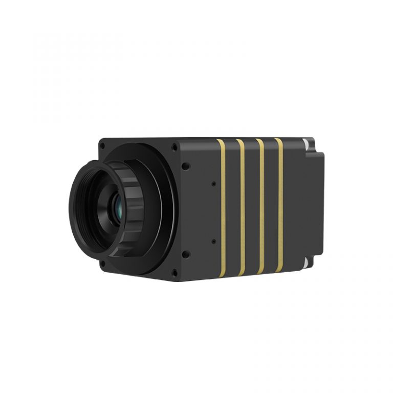
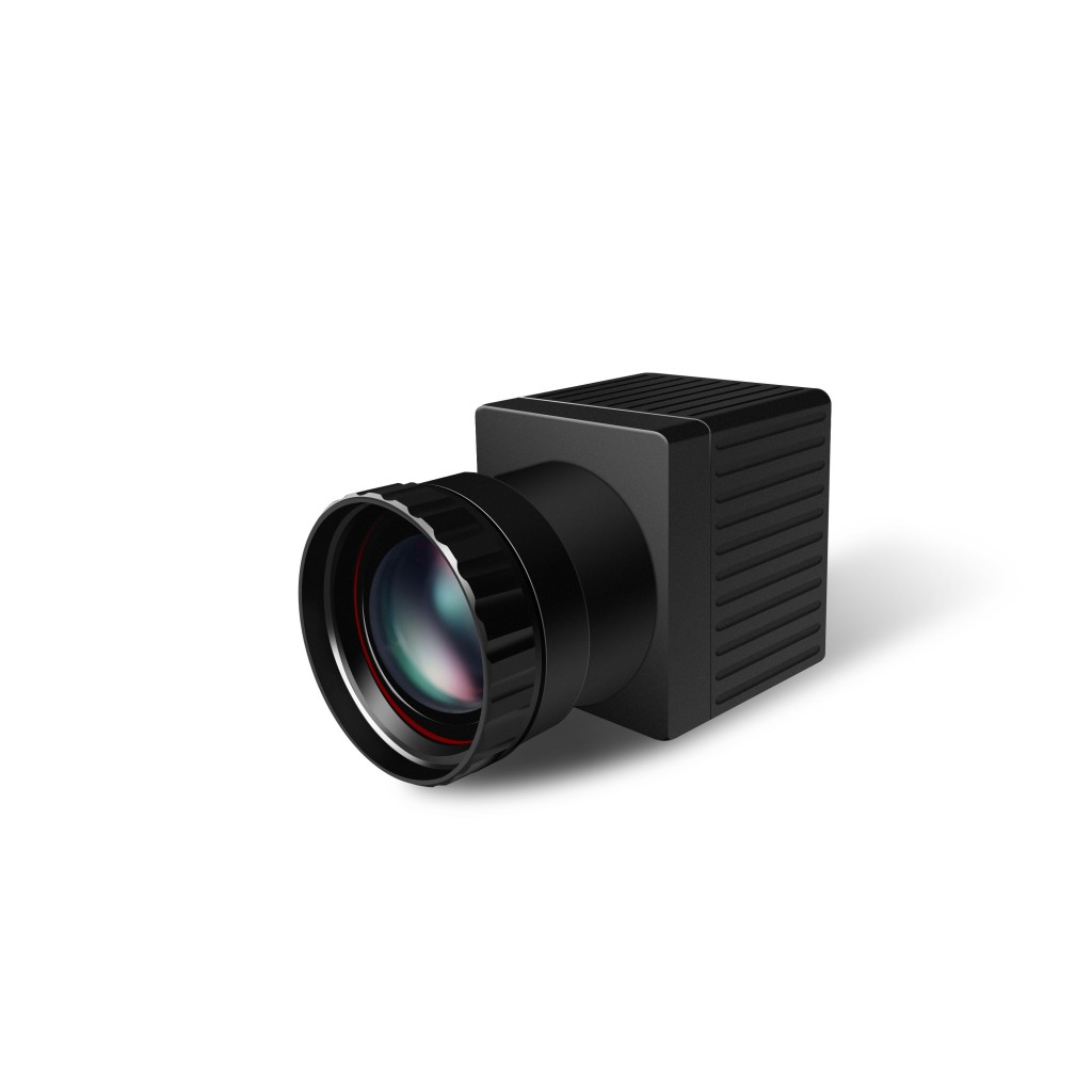
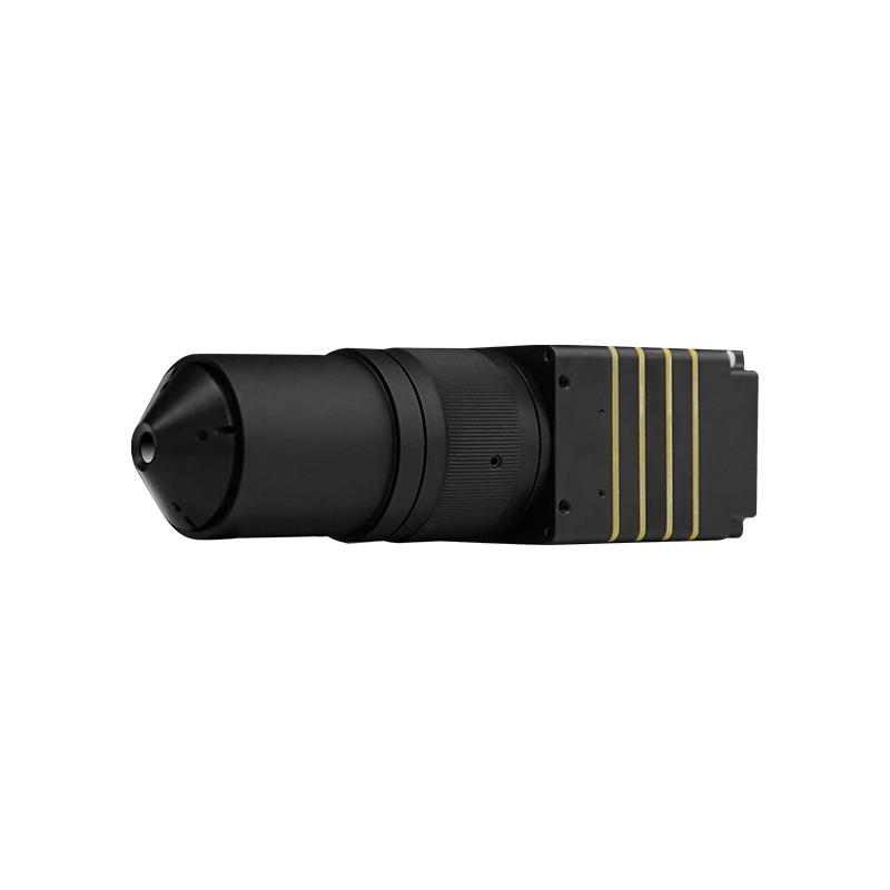
Infrared Thermal Camera Module-
-
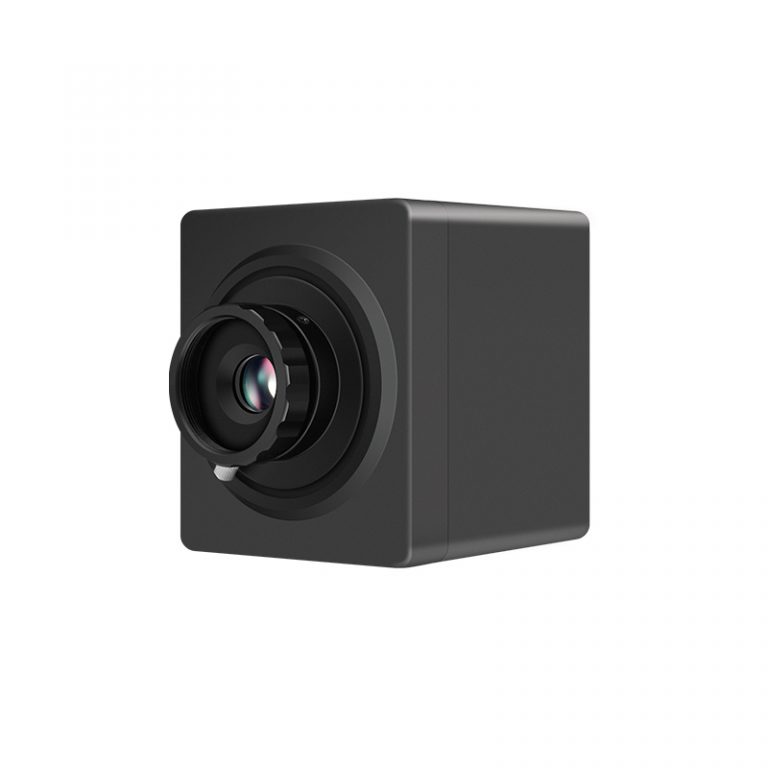
On-line Temperature Measuring T
-
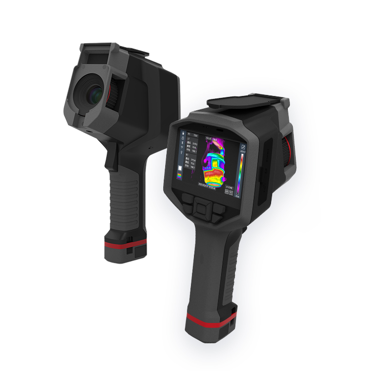
Professional Handheld Thermal C
-
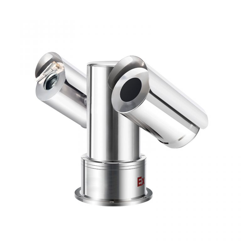
Bi-Spectrum Explosion-proof The
-
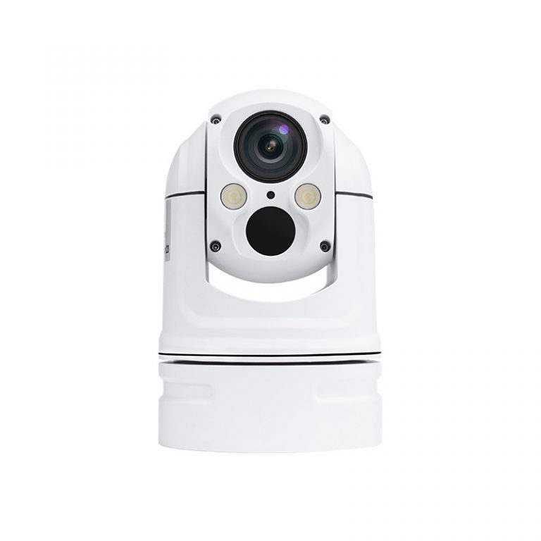
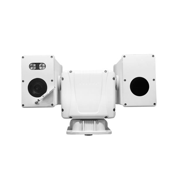
Small Bi-Spectrum Globular Ther
-
Big Bi-Spectrum Globular Therma
-
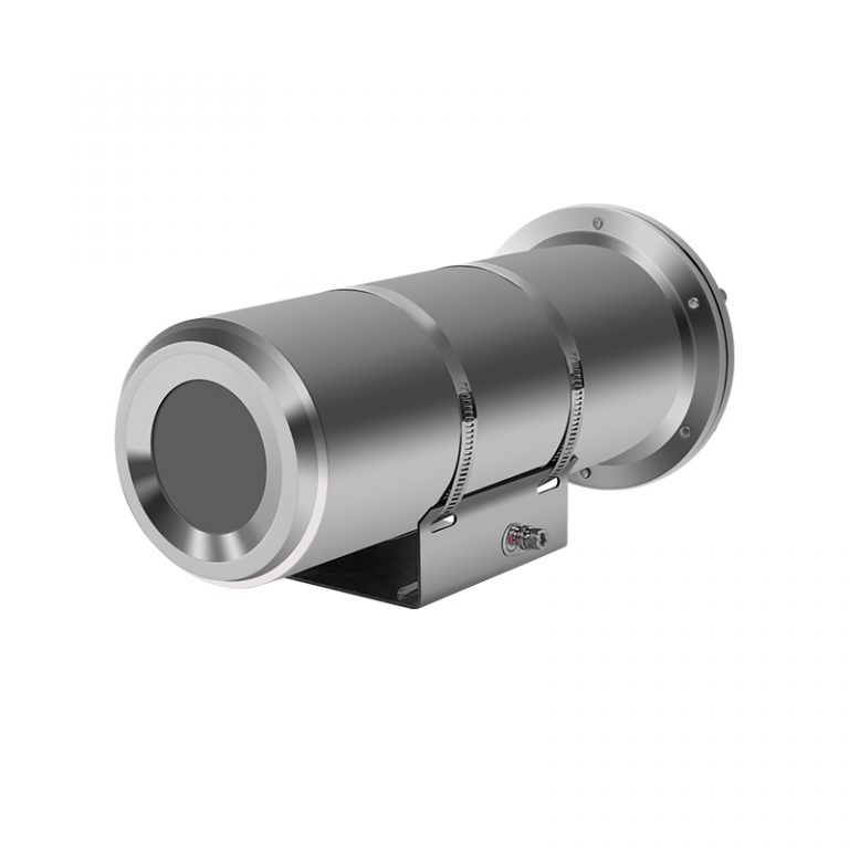
Monocular Explosion-proof Therm
-
Yoseen Infrared Thermal Camera
-
Bi-Spectrum Thermal T-Camera
-
Blast Furnace Monitoring Therma
-
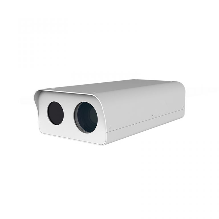
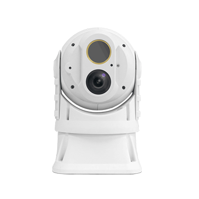
Bi-Spectrum Cabin Thermal Camer
-
-
Solutions
-
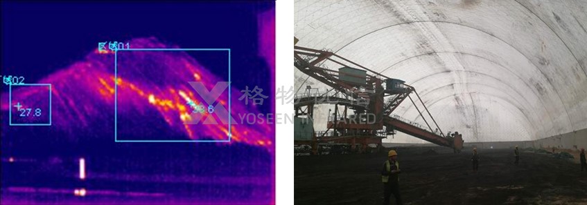
Prevention Solution of Coal Bun
-
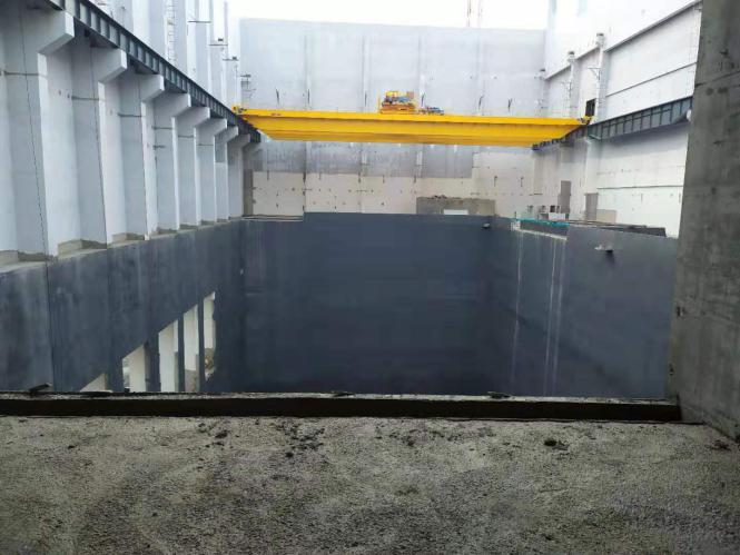
Garbage Power Station Dump Pit
-
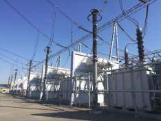
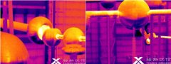
Transformer Substation Thermal
-
Converter Station Infrared Ther
-
Electrolytic Aluminum Productio
-
Infrared Thermal Camera To Ensu
-

Infrared Thermal Camera Helps B
-
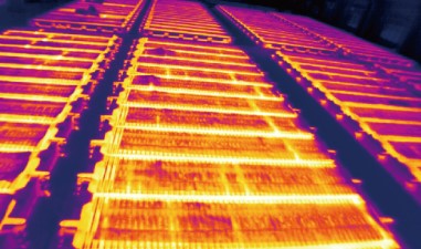
Factories Battery Warehouse The
-
Battery Warehouse Thermal Imagi
-
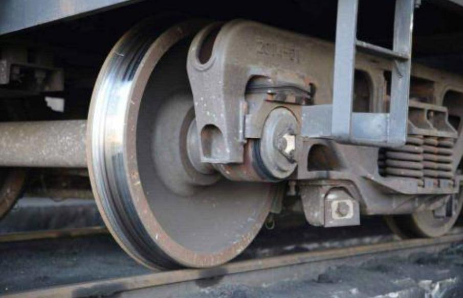
Train Wheel Hub Infrared Temper
-
Power Distribution Cabinet Ther
-
Intrinsically Safe Infrared the
-


 鄂公网安备 ******号