1. Program Background
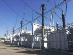
The main transformer, referred to as the main transformer, is the main step-down transformer used for transmission and transformation in the substation, and is also the core part of the substation. The capacity of the main transformer is generally large, and it requires high reliability in operation. Once the fault occurs, it will cause great loss. If not, it may cause equipment failure. Or it could cause a fire and endanger normal transportation. The main transformer has the following faults:
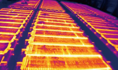
Blockage of radiator caused oil temperature rise of main transformer
A fault caused by a decrease in the insulating effect of solid materials
Before the failure of the main transformer, it is always accompanied by the increase of its own temperature. Therefore, in order to take effective protective measures, it is an effective means to judge according to the temperature of the main transformer. When the temperature reaches a certain high temperature value, the main transformer substation is judged to be abnormal, and corresponding measures should be taken to eliminate safety hazards.
2. Traditional Solutions
In order to accurately grasp the working conditions of the main transformer substation and find out the problems in time to avoid the property and safety losses caused by the abnormal work of the main transformer substation, various power stations take a variety of measures, among which the temperature of the main transformer is measured by the temperature sensor to judge the working status of the main transformer.
At present, the temperature measurement of the primary variable pressure device in a substation is under the pressure gun. When the temperature of the primary variable is too high, the fire control water gun will automatically trigger the water jet to cool down the primary variable inlet line. When the temperature measurement sensor is inaccurate or abnormal, the loss caused by fire water cannon trigger is very serious. Therefore, a set of more effective methods are needed to measure the temperature of the main variable.
Shortcomings of current detection methods:
Ø local temperature, cannot pass comprehensive main transformer temperature field information to determine the working state of it;
Ø temperature misjudgment mobilized fire water cannon processing loss is bigger.
3. Infrared Thermal Imaging Solution
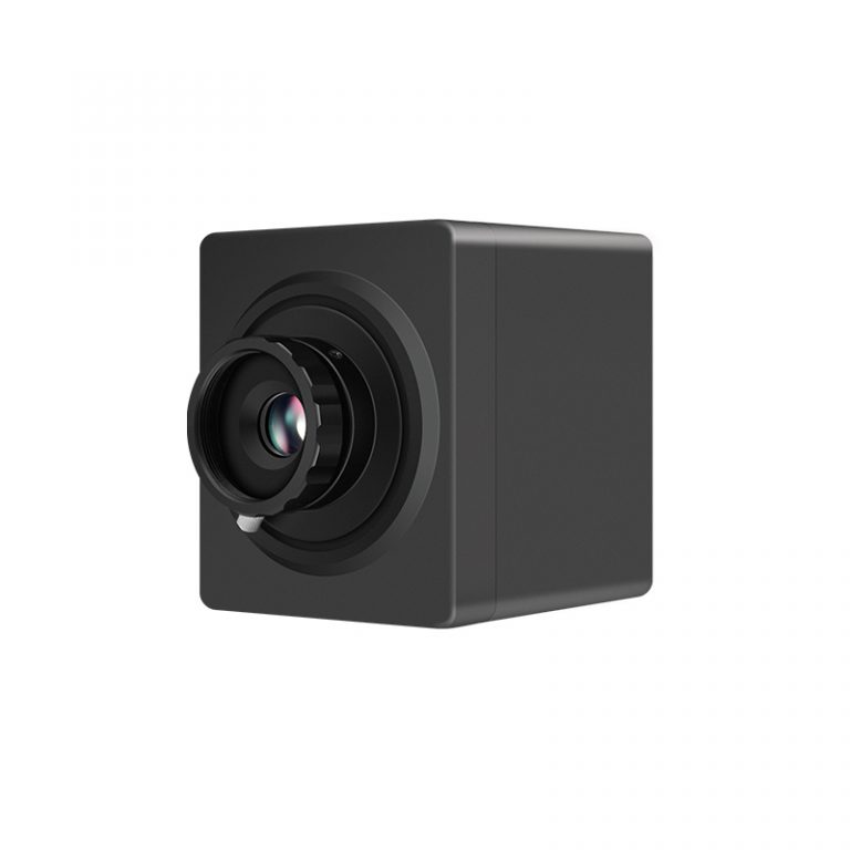
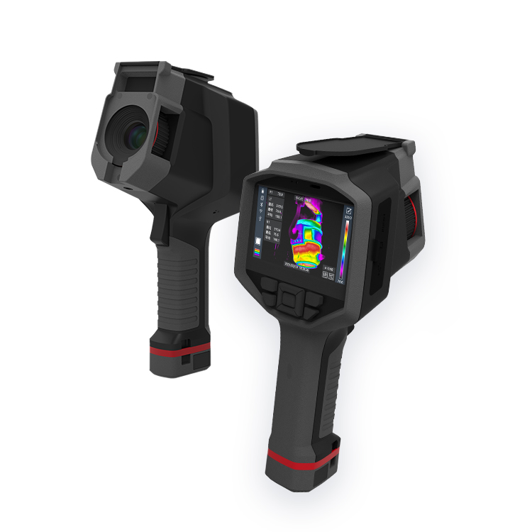
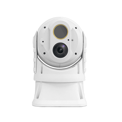
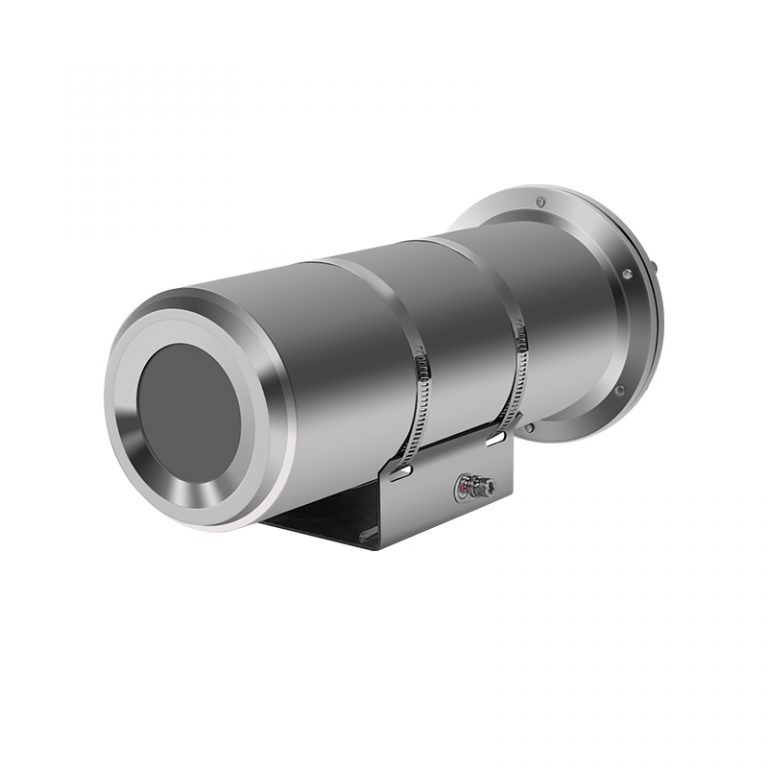
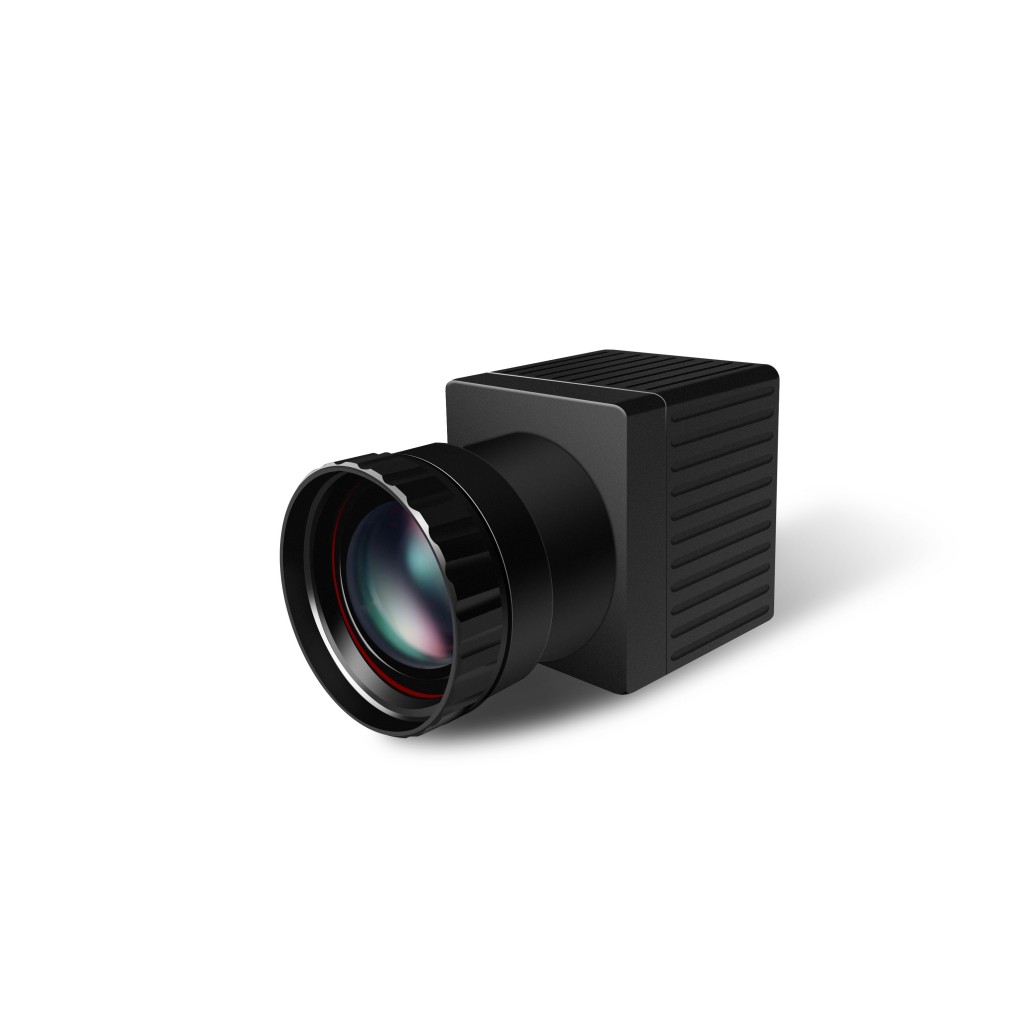
When designing the on-line thermal imaging temperature measuring system of power station, we adopt the system solution of front-end infrared thermal camera + back-end processing software. The system solution of front-end infrared thermal camera + back-end processing software can store video images and display them in real time through the display. The design method of separating front-end acquisition and back-end display also enables the staff to stay away from the scene of the dangerous work area, and the operation status of the equipment can be known in the control room, which is safe and efficient.
3.1 Dual-light monitoring method
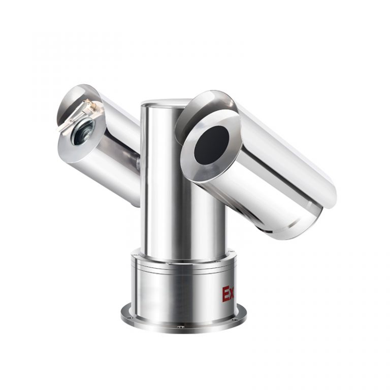
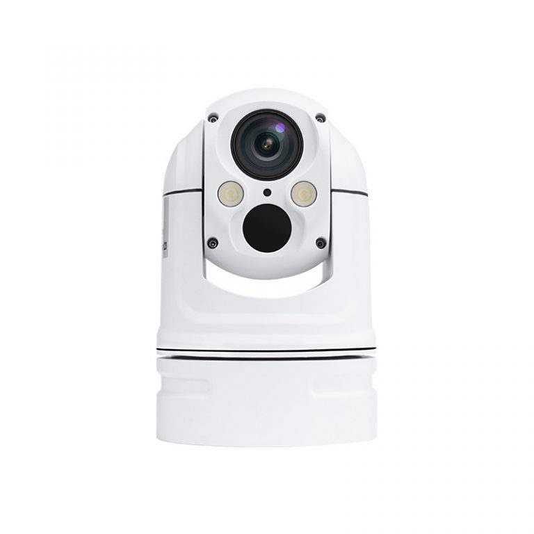
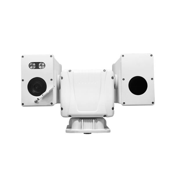
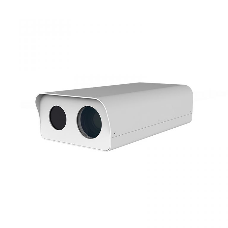
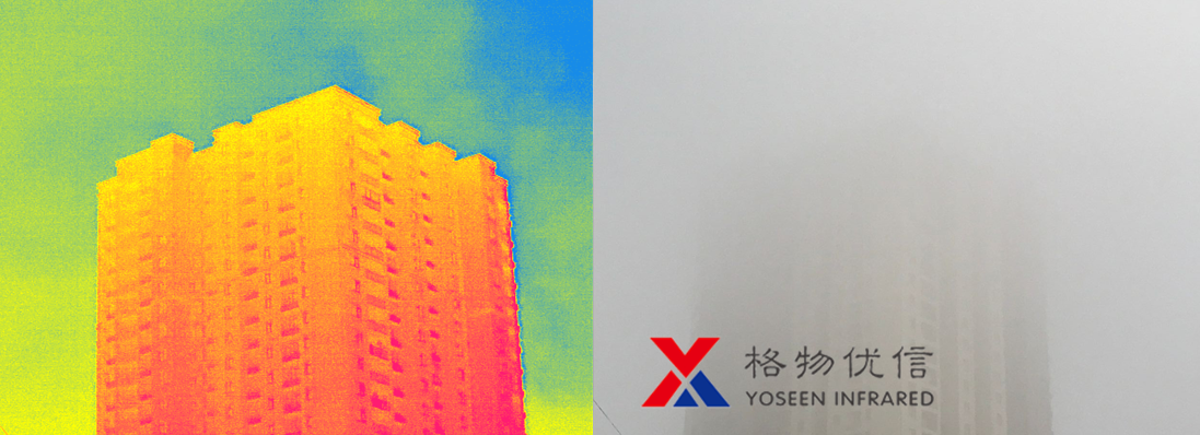
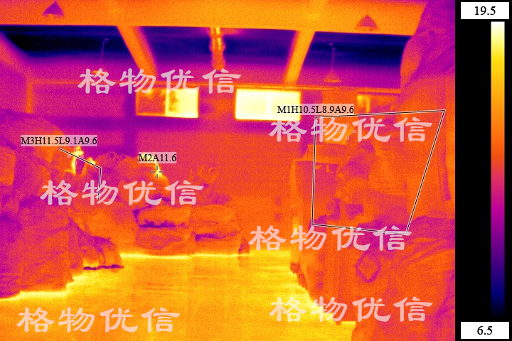
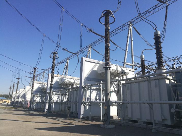
The main transformer substation adopts infrared light + visible light dual spectrum monitoring mode to monitor the temperature field of the main transformer through infrared light. In case of abnormal temperature, an alarm signal is given to remind the staff to take effective measures. Visible light monitoring is assisted to monitor the situation within the field of view in real time, so that the staff can see the surrounding situation of the main transformer substation more clearly and make a correct judgment.
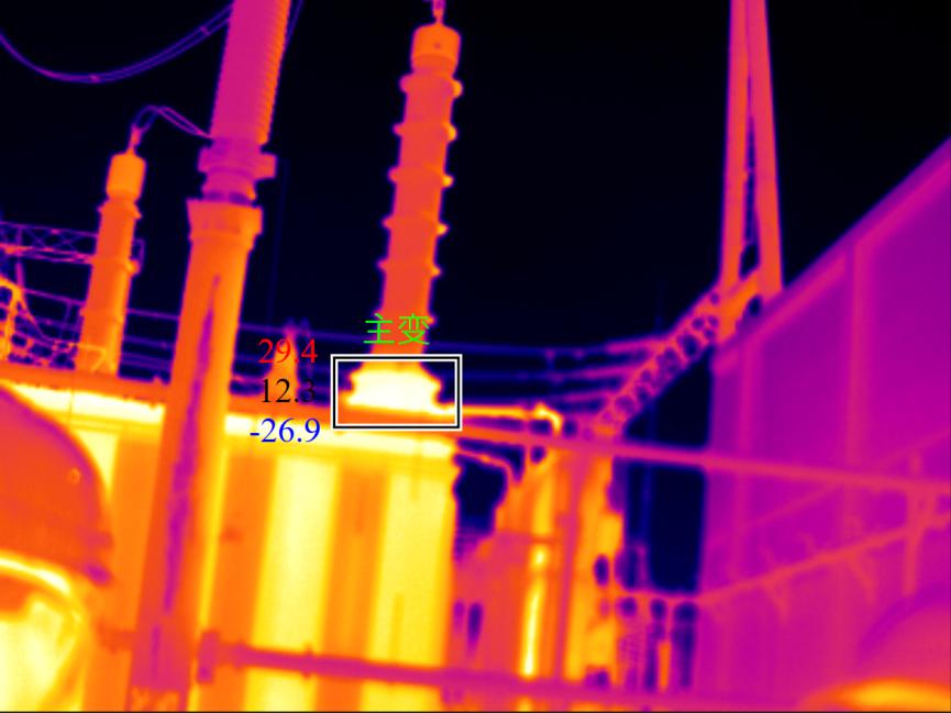
The main change under the dual - light infrared thermal camera
3.2. Add temperature measurement object
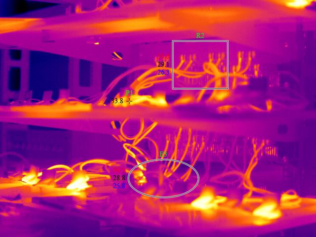
Add a host to become a temperature measuring object
3.3 Linkage of alarm signals
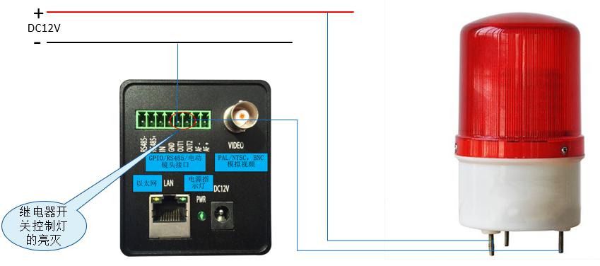
Alarm signal output
4. User Benefits
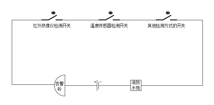
Considering the user's actual usage, and the system reliability and economical consideration of the project, we will keep the original in the substation main transformer monitoring ways of monitoring to detect the infrared thermal imaging detection of signal and the original way of monitoring signal processing in series in the same management system, and that when there is alarm all monitoring way to trigger the fire water cannon for processing.
Various monitoring methods are connected in series to control the call of fire water cannon
This way can effectively avoid the unnecessary call of fire and water cannon caused by the misjudgment of a certain monitoring method, which costs manpower and material resources; At the same time, the original system will be used to save resources.
Product Parameters
FEATURES |
DS-SM384D |
DS-SM640D |
||
Thermal Imaging Parameters |
||||
Resolution |
384×288 |
640×480 |
||
NETD |
≤50mk@300K,f1.0 |
|||
Frame frequency |
50Hz |
30Hz |
||
Wave band |
8-14μm |
|||
Temp range |
-20℃~150℃/0℃~300℃/60℃~600℃ |
|||
Camera lens |
Support multiple camera options |
|||
Temp measuring ways |
Points & areas measuring |
|||
Temperature display |
Global high and low temp tracking, point/line/polygon temp measuring templates, multiple objects can be added, set independent threshold range, sampling period and draw historical temp curve template, set multiple shielding areas |
|||
|
Focus Mode |
Electric/manual, electric lens supports autofocus |
||
|
Image enhancement |
Adaptive drawing, manual enhancement, electronic zoom |
||
|
Color palette |
White hot, black hot, iron red, red saturated, user-defined and others
|
||
|
Video output |
100M Ethernet +PAL analog video, with temp measurement area display |
||
Digital zoom |
x2, x4 |
|||
|
Visible Light Parameters |
|||
|
Image resolution |
1920*1080 |
||
|
Resolution |
2 million pixels |
||
|
Sensor type |
1/2.8’’ Progressive Scan CMOS |
||
|
Camera lens |
4x optical zoom, f=2.8-12mm (customizable) |
||
Horizontal view angle |
115°~33.8° (wide angle - far view) |
|||
Close range |
10mm~1500mm (wide angle - far view) |
|||
Zoom speed |
About 1s |
|||
MIN illumination |
Color: 0.05lux, black and white: 0.01lux, white light or infrared supplementary light: 0Lux |
|||
Holder Performance |
||||
Control |
Autonomous platform software, or HAIKANG client, or 485 line |
|||
Communication interface |
Network output |
|||
Command control |
The motion direction, angle, speed, preset position, cruise scan and initial action of power on of the holder can be controlled by software function interface |
|||
Preset points |
256 preset points, accuracy < 0.05 ° |
|||
|
Cruise scanning |
6 pieces, each can set 16 preset positions, preset time adjustable |
||
Automatic focus speed control |
The control speed is automatically adjusted according to the length of the focal length of the white light |
|||
|
Vertical angle |
-20°(look down) ~ +90°(look up) |
||
|
Horizontal angle |
360°continuous rotation, without monitoring blind area |
||
Vertical rotation velocity |
Keying 100°/S, manual 0.5° ~ 80°/S |
|||
Horizontal rotation velocity |
Keying 100°/S, manual 0.5° ~ 80°/S |
|||
AUTO rollover function |
Achieve 180° automatic rollover continuous monitoring in vertical direction |
|||
Power on operation |
The initial action of power on the product can be set |
|||
Installation way |
Supports vertical and upside-down installing |
|||
LED |
Support double LED supplementary lights |
|||
Network Function Processing |
||||
Data interface |
100M dual network output |
|||
Video processing |
H.264/MJPEG |
|||
Image output |
Main stream: 1280 x 720; Sub code stream :640 x 360, 352 x 288 |
|
||
Network protocol |
TCP/IP,HTTP,DHCP,DNS,DDNS,RTP,RTSP,PPPoE,SMTP,NTP,UPnP,ONVIF |
|
||
Business functions |
Support WEB configuration, OSD, real-time video transmission, movement detection and IO alarm linkage front-end storage, front-end storage playback/download, movement detection and IO alarm center alert and screen pop up linkage, MJPEG capture, unified client remote monitoring software, MYEYE platform and others; Provide complete SDK development kit (including JAVA) |
|
||
General Specification |
||||
Total weight |
≤2.8Kg |
|
||
Interchanger |
Built-in interchanger, single cable |
|
||
Wiring method |
Side outlet line or bottom outlet line is optional, side outlet line is aviation socket and aviation line, bottom outlet line is center hole lead line |
|
||
Shell material |
Magnesium alloy |
|
||
Appearance |
The paint surface of the machine is even and smooth without dropping paint |
|
||
Protective lens |
The double optical path has protective lens, including the germanium lens for infrared |
|
||
Power supply |
DC12V, power consumption of the whole machine<20W |
|
||
Protection level |
IP66, TVS 6000V anti-lightning, anti-surge, anti-surge. EMC meets CE/FCC standard |
|
||
Working temp |
-20℃~45℃, humidity <90% |
|
||
Secondary Development |
||||
Software support |
Provide complete related software or SDK development kit (including JAVA) for head control, visible light and thermal camera. |