Sintering machine is a sintering plant used to process iron ore powder in large and medium-sized metallurgical black sintering plant. At present, how to effectively monitor the cross section of the tailings and the clogging of the sintering table at the bottom of the sintering machine is an important means to improve production efficiency. The state and quality of sintering process can be judged by monitoring the shape of the section of sintered cake discharged from the sintering machine tail. The tail section of sintering machine can effectively reflect the changes of the material layer in the sintering process, and can directly reflect the quality of sintering, and people pay more and more attention to it.
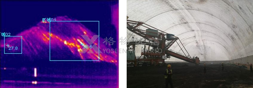
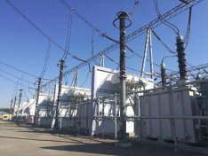
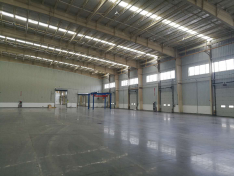
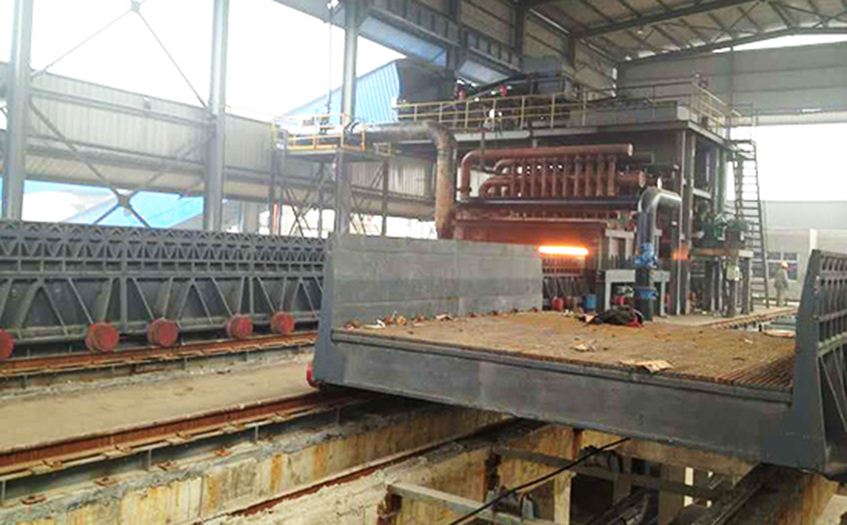
FIG. 1 Real scene drawing of belt sintering machine in steel works
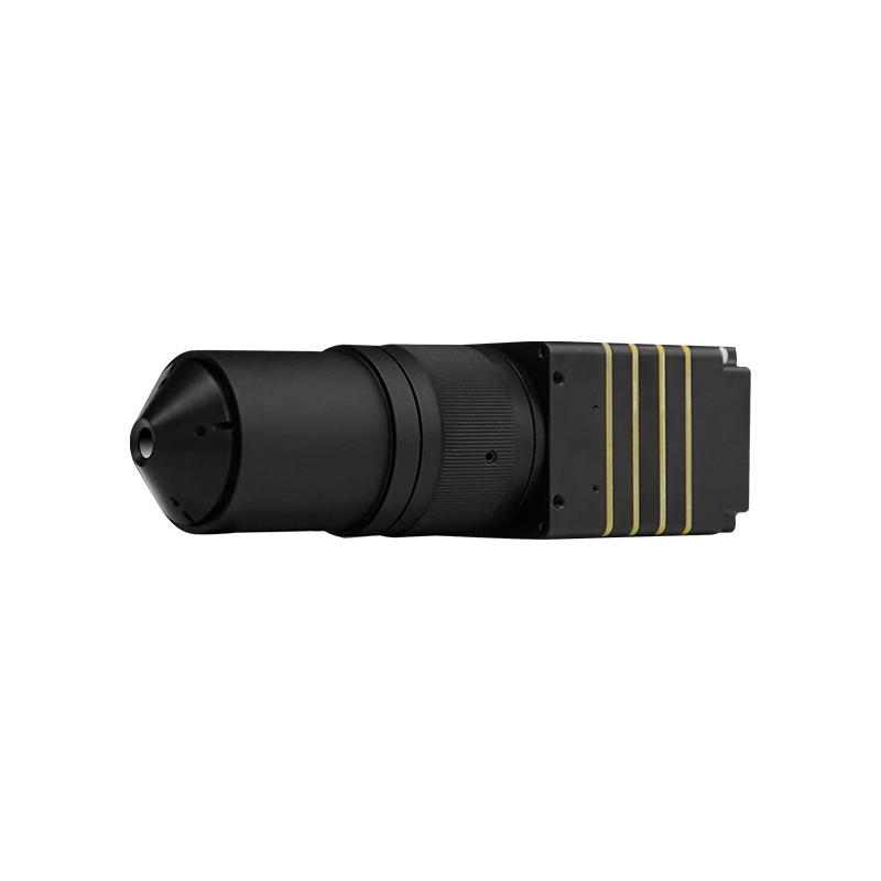
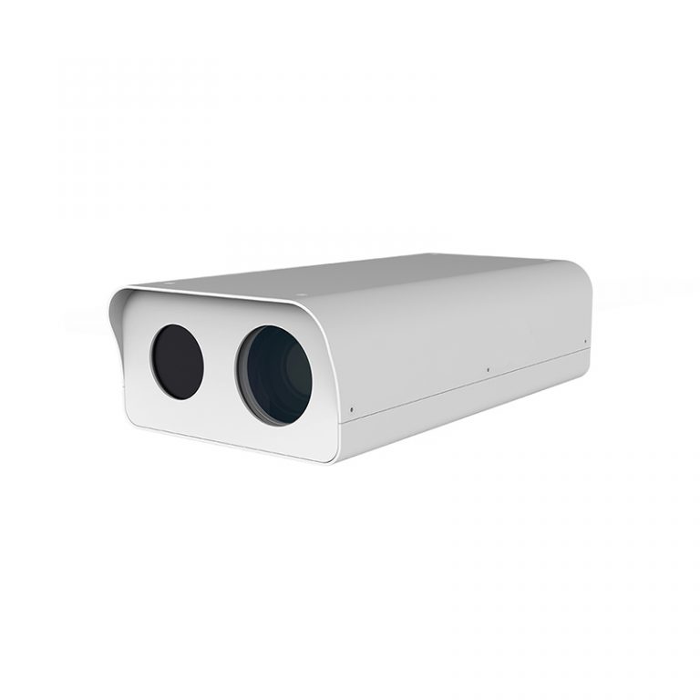
For the image observation of sintering machine, there are two monitoring methods at present: one is to use the ordinary visible light camera to obtain the visual image; Secondly, infrared thermal imager is used to obtain thermal images. The image recognition system of sintering tail section photographed by visible light camera can only recognize high temperature images, but can not make accurate judgment on medium and low temperature images, nor can it obtain all the information of thermal state of the section. Infrared thermal camera can be used to monitor the seam section of sintering machine and the clog of sintering table at the bottom of sintering machine on-line, which is of great practical significance to improve sintering production efficiency, ensure sinter quality and perfect the automatic control system of sintering production.
Infrared thermal camera can monitor sintering machine in all aspects
The special thermal imaging temperature monitoring system for the sintering machine of infrared thermal camera can solve the following problems:
1) The maximum temperature distribution of sintering machine section and temperature curve changing with time;
2) Longitudinal temperature distribution of sintering machine section and temperature curve changing with time;
3) The tail section of the sintering machine and the relative position of the red tropics of the sintering table and their changing trend with time;
4) Relative width and variation trend of red tropics over time;
5) Relative burning degree of mixture layer and change trend with time;
6) Establish a sinter quality prediction model;
7) The drum strength and FeO content of sinter are predicted online, and the trend of these sinter quality indexes changing with the production process is given to provide basic information for adjusting and optimizing sinter quality.
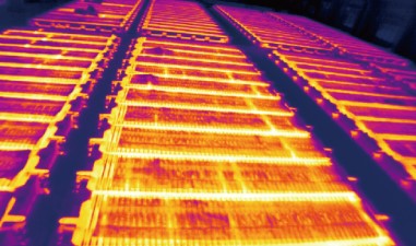
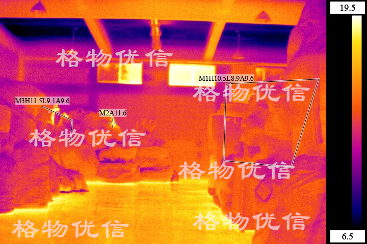
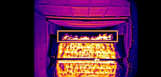
FIG. 2 Infrared thermal camera of testing and sintering in the sintering process of belt sintering machine
Infrared thermal imager can provide important technical basis for the whole process intelligent control
Sintering machine is according to certain proportion coordination of iron ore powder and solvent, powder, granule solid fuel after adding water mixing system grain of tile in sintering machine such as the car, and then the ignition, on the surface of the material at the bottom of the layers in convulsions at the same time, the coal layer surface is lit solid fuel combustion zone, with the help of high temperature burning, the sintering raw materials will occur between the composition of the corresponding physical and chemical changes, and partial melting or softening and generate a certain amount of liquid phase, particles will not melt the stick into pieces, each other become the sinter.
With the completion of upper solid combustion, it marks the completion of sintering process, which is also one of the most important monitoring Windows of sintering quality information. It is of great significance to control and optimize sintering process and sinter quality by obtaining infrared thermal image of sinter tail section and judging sinter temperature distribution information of sinter tail section.
Product Applications
Blast furnace burden surface, steel ladle, converter monitoring and others in harsh environment
Model |
M640D800/1600 |
M384D1600/800 |
|
Infrared resolution |
640x480 |
384x288 |
|
Pixel size |
17um |
||
Frame frequency |
30Hz |
50Hz |
|
Working band |
8~14um |
||
Field angle |
100°* 78°, diagonal 115 ° |
||
Temperature range |
80~800℃, 160-1600℃ (customizable) |
||
Temperature accuracy |
±2℃ or ±2%, can be raised to ±0.4℃ |
Image |
|
Imaging distance |
About 20 times focal lengths to infinity |
Temp measuring template |
Global high and low temp tracking, point/line/rectangle/ellipse temp measuring template, and tracking in template |
Image enhancement |
Adaptive drawing, manual enhancement, electronic zoom |
Color palette |
White hot, black hot, iron red, red saturated, user-defined and others
|
Focus Mode |
Electric/manual, electric lens supports autofocus |
Data |
|
Single frame temp |
PNG / BMP/ JPG image format with temperature information
|
Temperature flow |
Total radiant temperature information storage |
Digital video |
H.264, RTSP stream media protocol, MP4 files, HDMI output interface |
Electrical interface |
|
Power supply |
DC9~15V, typical power consumption 2.5W@25℃ |
Analog video |
NTSC/PAL compound video output |
Ethernet |
100/1000 Base, TCP, UDP, IP, DHCP, RTSP, ONVIF, etc.,provide SDK development kit |
Environmental parameters |
|
Humidity |
Non - Condensing 10%~95% |
Temp range |
Operating temp: -10~+60℃, Storage temp: -40ºC~+85℃ |
Level of protection |
IP54, Impact resistance: 25G, Vibration resistance: 2G |